Fig. 48
As original motivation for this work was the desire make something useful for the conservation of the Nature, that has been so attractive for me of since childhood. At the moment many people are concerned with continuously updated information about the growing deterioration of the natural environment, caused by the progress in the development and implementation of numerous mechanisms, working on energy sources that pollute the environment. Among of such people has proved to be also the author of this work.
At the first stage of the work came the idea – “Is it possible to use the mechanical advantage of levers with unequal arms for ensuring prolonged rotation of the motor rotor?”
It quickly became clear that the same ideas have inspired the people many times at last 2000 years, up to date, and manifested in plenty vain attempts to create a “perpetual motion machine”. In The USA there is even a museum [1], which shows a lot of historical layouts of these “engines”. Such engines cannot operate. This matter is explained by a fundamental law of nature - the Law of conservation of energy -, and by the consequence from it consists in that, since the gravitational field is a potential field, the work of its forces on the movement of a material point along any closed path is equal zero. The latter fact concerns to each of the movable loads of rotors such devices.
But after this matter became clear, another question arose: “Is it possible in such devices, using the mechanical advantage provided by the levers with unequal arms of rotation about single axis, partly harness the energy of gravitational influence on masses of movable loads jointly with another source of energy, which is also ecologically clean energy source?” The Law of conservation of energy applies to isolated systems. But, if we use the systems which are not isolated? That is, if we implement the interaction of two or more sources of energy emanating from the different systems, the violation of the Law of conservation of energy will not occur.
For example, for the operation of hydraulic turbines people successfully use from ancient times the kinetic energy of water falling from a great height, that is the energy of the gravitational field of the Earth, at the combined action of another or by the others natural sources of energy which realize the water rise to this height, and at the same time provide to it the corresponding potential energy.
At searches solution of this problem have been considered the device, which is sometimes called “Indian wheel”. This appliance, known by the description of the Indian astronomer Lalla (748 NE) [1], is one of the earliest attempts of the man to create a perpetual motion machine.
At this has been made the calculation in general form of the appliance, similar in its mechanical characteristics to the aforementioned device. Technical drawings of this hypothetical device considered in the calculation are shown in Figures 1, 2, 3. The results of the calculation are given in sections 3, 16, 4, and 6 of the main text.
In consequence of the calculation were obtained digital values torques generated by each movable load, depending on its position relative to the rotor axis during rotation. These data allowed evaluate in numerical form the contribution of each load into the total amount of the net torque. The loads moving in the sector A4 — O — A7 ( Fig. 2 ), where their centers of mass, move along the circumference of the maximum removal from the motor rotation axis (Rmax), provide the greatest positive contribution to the net torque. But the loads moving in the sector A8 — O — A11 ( Fig. 2 ), where their centers of mass are also moving along the circumference of the maximum removal from the motor rotation axis (Rmax) create the largest negative (inhibitory) contribution into the net torque. In general, the individual torques generated by the all moving loads due to influence of gravity, in accordance with their signs and magnitudes, mutually cancel each other out and nullify the net torque.
Analysis of the digital data resulting from the calculation has shown that such a device is a technical system with multitude states of stable equilibrium, the number of which is equal to the number of the movable loads which create the net torque on the motor shaft. Output from any of these states of stable equilibrium and subsequent rotation can only occur at the sufficient impact of the force impulse coming from another (external with respect to this gravitational) energy source. After termination the action of the external force, the rotation must inevitably cease in one of the possible states of stable equilibrium. This is fully consistent with the law of conservation of energy. However, the calculation showed that in such systems is possible the mutual harnessing kinetic energy of direct gravity impact on masses of the movable loads with energy of other source to ensure the prolonged rotation of the motor rotor. At this was found out, in which specific sector of rotation is the most efficiently to introduce an external force impact in order eliminate the most braking effect of gravity on the moving there loads. If by using an external energy source is carried out counteraction the influence of gravity on the masses of loads moving in this rotation sector, and at this the centers of their masses are became as close as possible with the axis of rotation of the rotor, the state of the system will be changed. The centers of masses of the loads, moving in the other sectors of the rotation, will become bonded by the unequal-arm levers relative to the rotor axis of rotation, whereby in the system will not be longer the states of stable equilibrium, and the net torque will not more be equal zero, that is, in the system will come into being the constant rotational force generated by the direct impact of gravity on the masses of movable loads, moving in the remaining sectors of the rotation.
Regarding of the quantitative characteristic of the resultant rotating force provided by the direct impact of the gravitation on the masses of the movable loads which mutually bonded under such conditions by unequal arm levers of rotation, the calculation has showed that the magnitude of the net torque on the motor shaft is directly proportional to the product of the value of magnitude of the mass of a load on the value of the ratio Rmax/Rmin.
At this, it is possible and desirable to introduce impact of the external force in addition to the direct influence of the gravitation on the movable loads, moving in the remaining sectors of rotation. As a result, the joint use of two different renewable energy sources can provide very efficient engine operation.
In basic text of the website are considered several variants designing rotors of motors, where as another source (external to gravity) of energy impact is used the energy of force interaction of permanent magnets. In these embodiments all movable loads of the motor rotor and the surrounding it stator are equipped by permanent magnets. Exception of the retarding contribution gravitation from the net torque is provided in the above-mentioned rotation sector by means of using the phenomenon of levitation permanent magnets.
Since, in accordance with Newton's law of universal gravitation, the force of gravitational attraction is directly proportional to the mass of material object, any engine developer who wants to use the energy of the gravitational field should strive to create such a design, where the objects, which must be subject to the impact of gravity, would have had a greater mass.
At the initial stage of works on the engines design proposed in this site has been considered the motor rotor design shown in Fig. 4 (Chapter 5 of the main text). A feature of this design is that on the motor rotor shaft is planted rigidly a couple of identical disks, and into the space between the disks are moving the loads which mechanically bonded with the disks. This mechanical bond is provided by the fact that the loads are equipped (at their ends) by the wheels which allow them to move along inclined paths, built-in the disks, and transmit by identical way the weight efforts to the disks, ensuring their rotation (the efforts determined by the gravitational effect on the centers of mass of the movable loads). Such an arrangement of the movable loads in the space between the paired disks enables the use the loads with a larger mass by increasing distance between the disks and increasing the diameters of the disks, that is limited to only by selected (permitted) dimensions of the entire device and by constructive requirements of ensure mechanical toughness.
Although at the beginning of engineering of gravity-magnetic motor was supposed use of the movable loads of cylindrical shape, that was reflected in the sketch shown in Fig. 4 , in the course of further work on the improvement of engine design has been found the possibility of application the loads of bar form. The use movable loads of the bar shape, instead of the cylindrical shape, not only increased the efficiency of power interaction of permanent magnets, but also opened up the possibility of further increase of the mass of the loads themselves. However at this, arose necessity in complication the design of movable loads - it became need to equip the loads by two axes with wheels on their ends rather than only by one axis, as it was earlier. The rotor design with the loads of bar form, and their features, are explained Section 19 (Fig. 44 ) of the main text.
*
* * *
The considered above possibility of harnessing the kinetic energy of the gravitational field of the Earth jointly with another source of energy, which is also environmentally friendly, and also the positive technical solutions of a number of constructive problems, which have been found in course of design of gravity-magnetic motors, especially the last recommendations for the rotor design with movable loads of the bar shape, may become possible and expedient for designing hydraulic turbines.
But if in all suggested variants of designing gravity-magnetic motors the formation of unequal arm levers of rotation between the centers of mass of movable loads occurs due to compensation of the direct impact of gravitation on the masses of loads moving in aforementioned (specific) sector of rotation - the compensation - which is implemented due to counteraction of the permanent magnets, but in the work of engines of the hydraulic turbines we have another opportunity to provide similar counteraction to impact of gravitation in such sector of rotation. Instead of using the phenomenon of levitation of permanent magnets it is possible to lift loads (rotor blades), during their moving in this sector, and to bring them closer to the axis of rotation of the rotor due to the partial use of water power falling from above. That is, at this, counteraction to gravitation will occur due to impact of the same initial source of energy - the gravitation. Namely this fact justifies the possibility of introducing of the strange phrase in the title of this section of the site - "Gravitation against gravitation".
* * *
Below are offered three variants designing rotors of hydraulic turbines, based on the above recommendations.
The main difference of the proposed options design of rotors for water turbines against the corresponding devices of constructions turbines, which are widely used at present, is in that the blades of the rotors are not bonded rigidly to the axis of rotation, but they are movable relative thereto. In process of the rotor rotation the centers of mass of the movable blades are changing their remoteness relative to the rotation axis of the rotor. The rotor design in the proposed embodiments provides conditions at which the movable blades, opposed to each other with respect to the rotor rotation axis, become bonded with the axis of rotation by unequal arms levers. This allows the use mechanical advantage of such kind levers. As a result, in addition to use, in current water turbines, of the kinetic energy of pressure the falling from height water on the rotor blades, is opened the possibility of harnessing of the kinetic energy of the direct effects of gravitation on the masses of the movable blades.
* * *
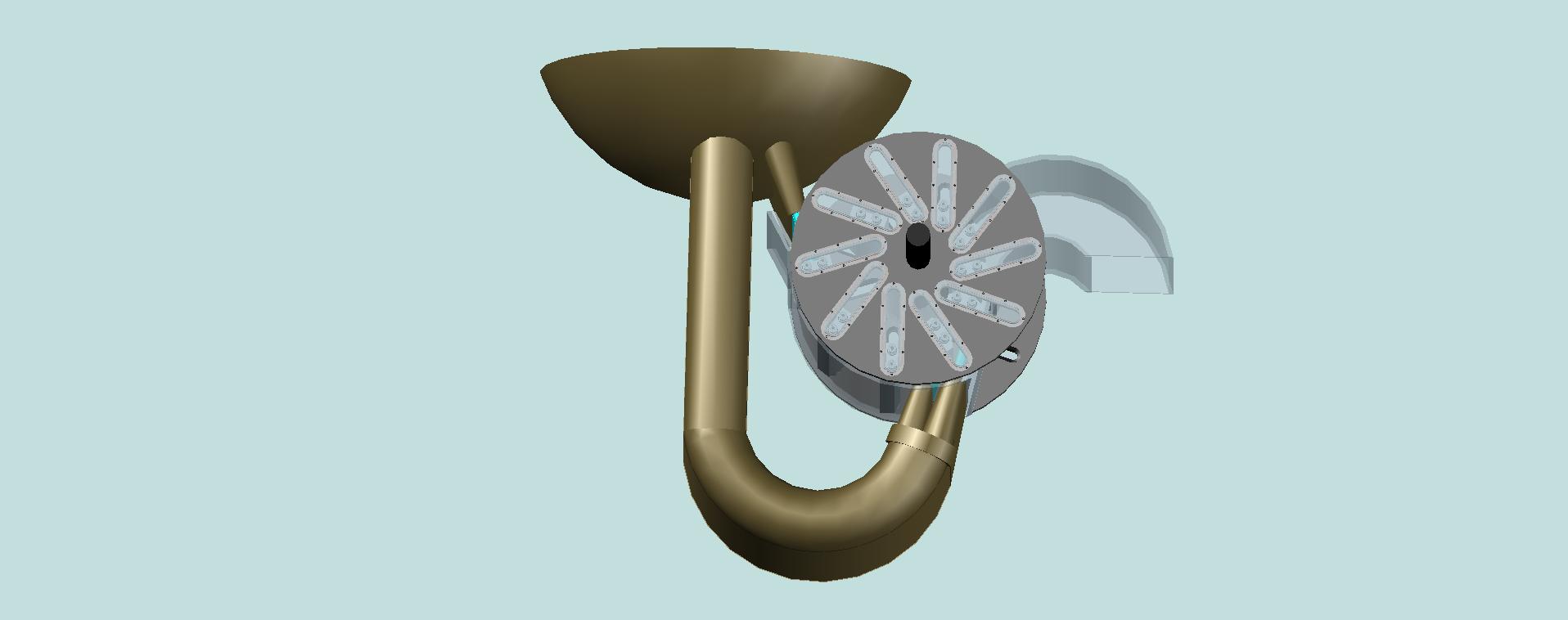
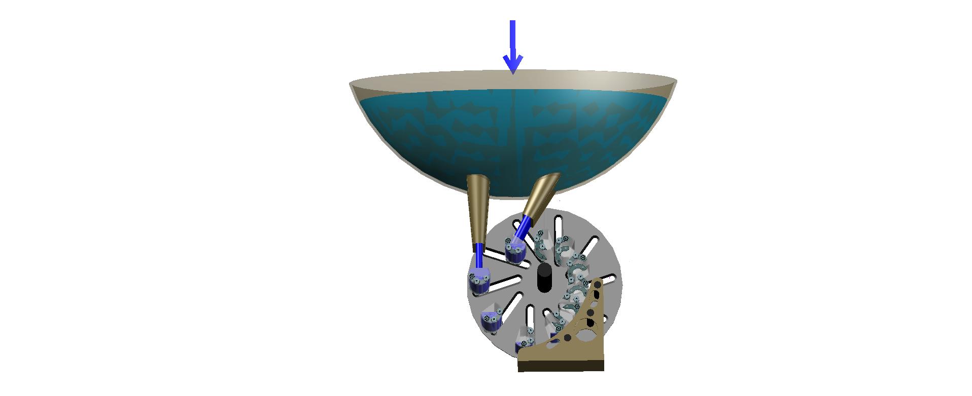
Consider the first variant device of rotor hydraulic turbine with movable blades.
This embodiment is characterized in that force impact on the movable blades of the turbine rotor is provided by flow of water outgoing from the three nozzles. The water pressure force is mainly determined by the value of the natural drop of water from a height to the place of a turbine location. The total water flow acting on the turbine rotor is guided and removed by a special casing.
In Fig. 48 is shown an overall view of such a device.
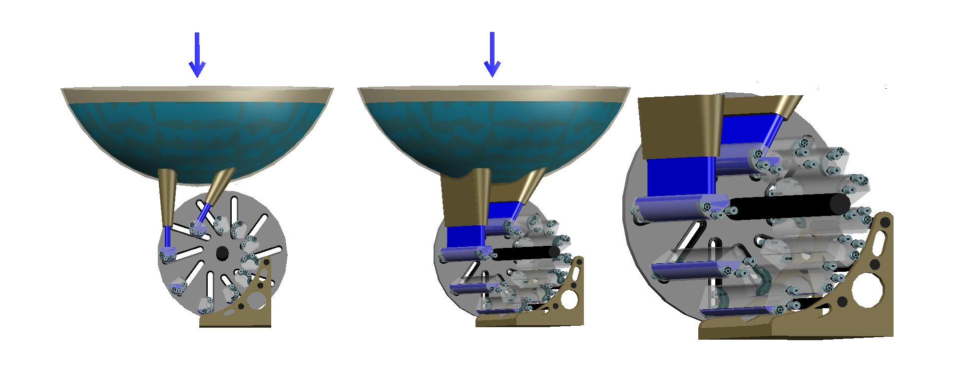
In Fig. 49 front disk of the device and the upper parts of the tube that delivers water are removed for clarity.
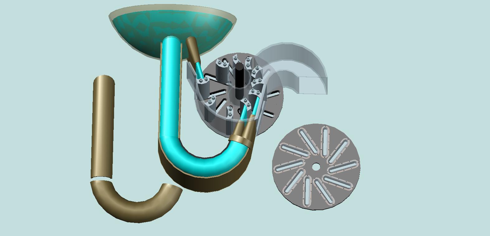
On the rotor shaft, perpendicularly to the axis of rotation, rigidly planted two disks. Into the space between the disks is placed plurality (in the above sketch - 10) movable loads - the rotor blades. The possibility displacement of the loads relative to the rotor axis, during its rotation, is provided by the presence of wheels on the ends of the loads moving along the 10 inclined paths embedded in disks. For proper impact of gravity on masses of the movable loads - rotor blades - the position of the rotation axis of the rotor, relative to the ground, must be strict horizontal.
Note:
Elements of the rotor structure providing required direction of water flow in space between the disks are shown on this and on all subsequent figures by semitransparent color for clarity.
The principle of action of the motor can be explained with the aid of figures 50 and 51, where is shown the cross section of the engine rotor by the plane parallel to the internal planes of the paired disks and passing midway between them.
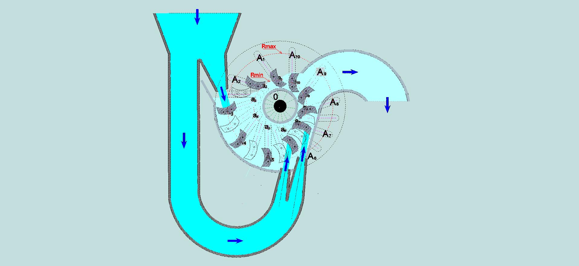
In the Fig. 50 is shown the cross-section of the conduit with three nozzles. The circumference, which is shown in the figures 50 and 51 by the dotted line of maximum diameter, conventionally reflects the projection of the disk on the cross-sectional plane. Cross-sections of the ten movable blades are shown by hatching of gray color, with the image of location center of mass of a load by the point of black color, and with the images, by black circles, cross-sections of the two axes equipped with the wheels at their ends (the contours of those wheels are shown in dotted lines). During rotation of the rotor, the centers of masses of the movable blades are moving along axes of the inclined tracks embedded into the disks. In the figures 50 and 51 are shown (by the dotted lines of red color) the circumferences of the highest possible and minimally possible remoteness of the centers of masses of movable loads (of the rotor blades) from the axis of rotation (“O”) → Rmax and Rmin. The axes of inclined ways embedded into the disks are conditionally shown by the dotted lines of crimson color. Cross sections of the movable blades into the intermediate positions of their movement are shown by dotted lines for clarity. By the symbols a1 — A1 … a10 — A10 are designated the places of feasible location of the centers of masses of the movable blades at their minimum and maximum removal from the rotor axis of rotation (from point “O”). The actual location of the movable blades, and accordingly of the centers of their masses, in the process of rotor rotation is determined by the power impacts, which will be discussed later. In the figures 50 and 51 are also shown cross-sections of the stationary casing and the rotating cylinder, which is rigidly coupled with two paired disks, and rotates together with them. These two devices provide the necessary input, direction, restriction, and output of the working fluid. The appearance of these devices is shown in Fig. 52.
In the Fig. 53 are shown the movable loads, which serve as the movable blades for rotor, and the disks (at left – is the view from the inner side of the disk, and at the right – is the view from outside).
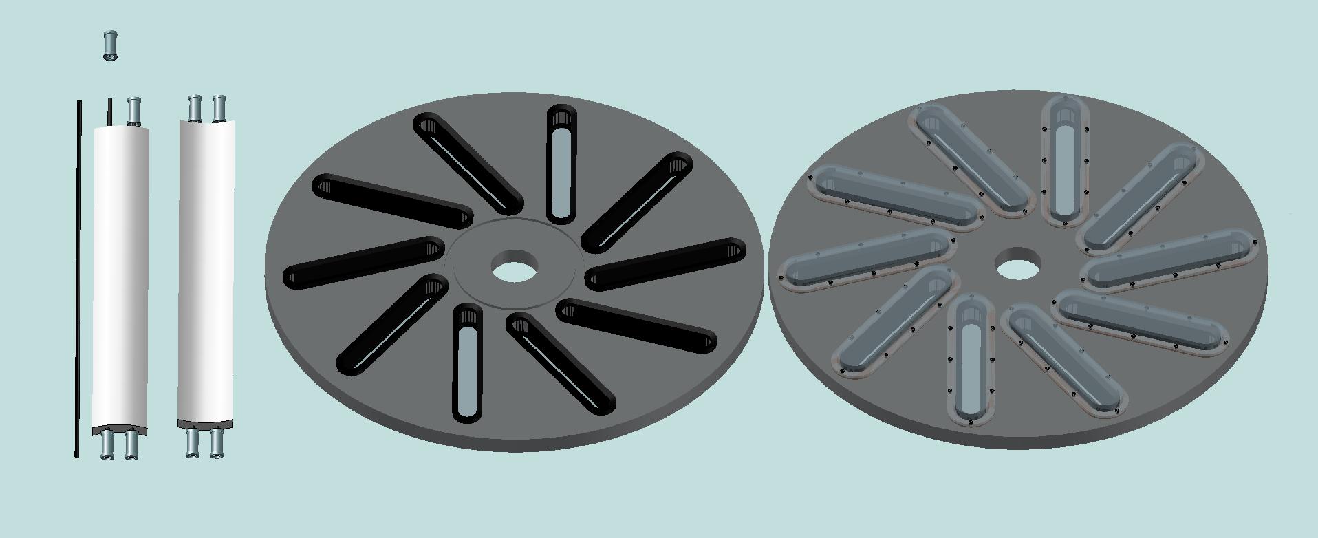
Each movable blade of the rotor is equipped with two axes, at the ends of which are fixed the wheels (bearings) providing the linear movement of the loads along the appropriate paths, built-in into the disks. On the outer sides of the disks these paths are hermetically closed by covers, in order to avoid outflow of the water. Of course, geometric shape of the movable blades can be improved by the experts, taking into account long-term experience in the development and operation of the existing water turbines. At this, the mass of the blades (and, accordingly, their weight) should be as large as possible.
Since in restriction and direction of the flowing water is involved the stationary device, shown in Fig. 52, then between it and the movable parts of the rotor is constructively inevitably the existence of a gap, through which the water will partly drain. Therefore, in the full engine structure, for directing this part of water to the general outlet flow, will be required an additional external housing which is not shown on the given figures.
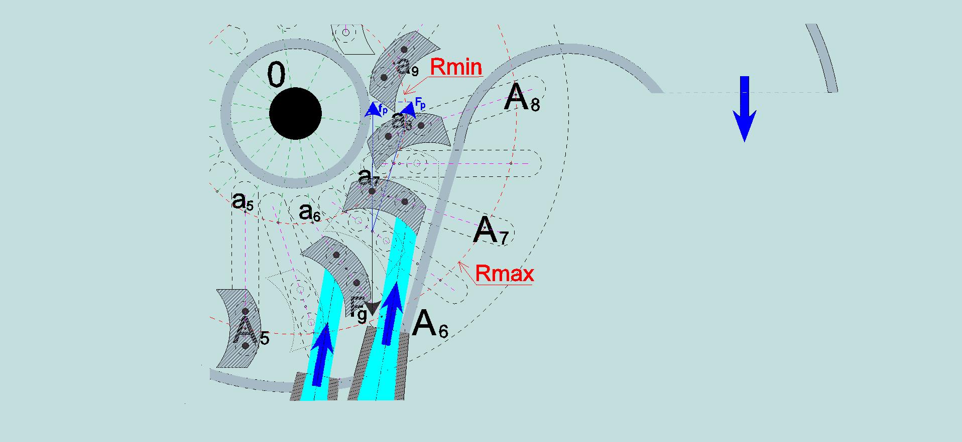
On the given above figures are not shown also the valves for blocking and adjusting the flow of water through the conical nozzles, required at the initial stages of installation and start-up of the turbine. Before start-up of the turbine in the space between the disks is no water and, accordingly, there is no water pressure on the movable blades (to loads) of the rotor. Under these conditions, the loads, which came to be in the space of the sector A6 – O – A8 (Fig.51), are in direct contact with the inner surface of the stationary device of direction and restriction of water, due to impact of gravitation. In order to avoid friction between the said contacting surfaces in the beginning of water input, it is necessary to supply water at first from the lower nozzles, at the overlap of supplying water from the upper nozzle. The water pressure flowing from the lower nozzles will ensure the compensation of gravitational impact to the loads during their moving in the sector A6 – O – A8. The surfaces of the movable loads will come off from the surface of the stationary device. The centers of masses movable loads will be shifting to the rotor axis (to point “O”, as it indicated in Figures 50, 51) , and the rotor will begin rotate due to the mutual influence of the kinetic energy impact of gravity to the movable loads, bonded by unequal-arm levers of rotation, and the kinetic energy pressure of water flows, emanating from the lower nozzles. Then, it should to open the valve of top nozzle. The additional pressure of flow water coming from above will significantly strengthen the net torque of the rotor.
*
Thus, the principled feature of the proposed design of the motor rotor with the blades movable relatively to its axis, that distinguishes it from conventional designs of currently operating currently turbine, is in that the centers of masses of the movable blades are turned out to be bonded by unequal-arm levers of rotation about a rotor axis. Mechanical advantage in force provided by unequal-arm levers of rotation leads to a significant increase of the net torque on the motor shaft.
As a result, the engine works by joint harnessing of two renewable ecologically clean sources of energy: the energy radiation of light (heat) from the Sun, which, through complex transformations, provides lifting the water to height, imparting her potential energy, and the energy of the gravitational field of the Earth, which, at such engine design, acts on the rotor blades not only by the conversion of the aforementioned potential energy into kinetic energy of falling water, but also due to the direct gravitational impact of the Earth on the masses of the movable blades.
* * *
It seems possible embodiment of the motor rotor, wherein the impact of water pressure is implemented by means of only one nozzle located in the upper part of the rotor.
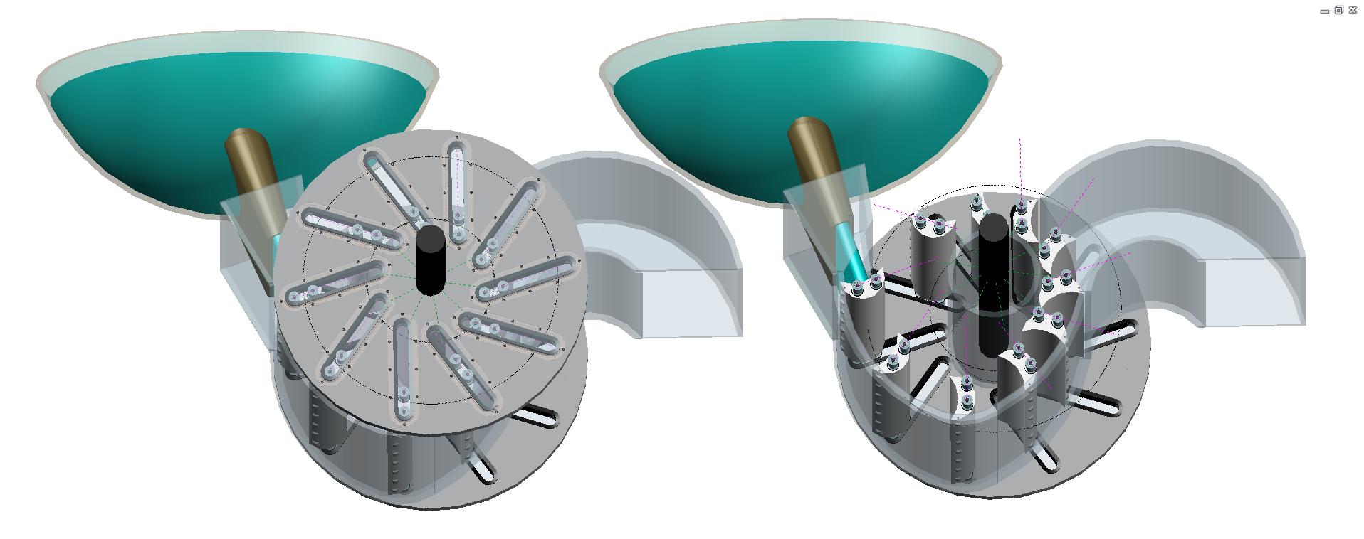
In Fig.54 is shown in two views such option of the motor rotor with only one nozzle designed to control the direction and increase velocity of water flow. It also may be seen the devices for direction, restriction, and output of water. For greater clarity, the devices directions, restrictions and output of water are shown in a translucent color, and the view in the right part of the Figure is shown without the front disk.
The question immediately arises. How is provided the solution of the problem with the direct touch of the lower parts of surfaces of the movable blades with the inner surface of the stationary device of direction and restriction water? - The problem, which must inevitably arise in the sector of rotation analogous to the sector A6 – O – A8 (Fig. 51). This problem must be particularly severe in the first moment of ensuring the water pressure coming from above, from the single nozzle. At this moment, the rotational force (torque) on the rotor shaft arises due to the perception of this pressure by the only one opposing blade of rotor. Into the sector A6 – O – A8, as yet, is no water and no other reason which could eliminate, or reduce, considerable friction of above-mentioned surfaces. The solution of this problem is possible, but for this, it will be necessary some complication the design of the movable rotor blades. It will be required equip every blade with additional axis with the wheels on it. This axis should be placed into the body of the movable blade, close to the side which could be directly touched the inner surface of the stationary device for direction and restriction of water. Thanks to the wheels on the additional axis the friction of sliding will be replaced by rolling friction, consequently, the friction will be considerably reduced.
In the Figure 55 are shown the cross section of the rotor in sector A6 – O – A8 and, in two views, the appearance of such movable blade with side wheels.
After a short time following the beginning of the impact of the water flow from the nozzle, the water will arrive into the sector A6 – O – A8, and will provide corresponding pressure on the movable blades passing here. The water penetration into sector A6 – O – A8 will reduce friction of the wheels which will be rolling along the inner side surface of the stationary device for direction and restriction of water, and, at the sufficiently high pressure of water to the movable blades, the wheels will fully come off from the inner surface of the stationary device, and the rolling friction will be totally discontinued. By reason of that the movable blades, getting into this rotation sector of the engine, will come nearer to the rotor axis, and at this, centers of masses of the most other movable blades will turn out bonded with its axis of rotation by unequal-arm levers of rotation. As a result, the sum of the individual torques generated by the direct influence of gravitation on the masses of the movable blades will create the resulting rotational force of large enough force. Its value is directly proportional to the product of the mass of a movable blade (of its weight) on the numerical value of the ratio of the lengths of the radii Rmax/Rmin (Fig. 55).
In the Fig. 56 are shown, in two views, the devices of restriction and direction of water: the one of which (ring-shaped) is rotating, being rigidly connected with the two rotating disks, and another is stationary.
In all the figures, these devices are shown by semitransparent color for clarity.
In the Fig. 57 is totally shown the cross section of the rotor by the plane parallel to the internal planes of the paired disks and passing midway between them. Streams of water providing rotation of the turbine rotor are conditionally shown by blue, and dark blue colors.
*
Thus, in this rotor design is also provided the mutual harnessing of the kinetic energy of pressure the falling from height water on the rotor blades, and the kinetic energy of the direct impact of gravity on the masses of the movable blades bonded with the rotation axis by the unequal-arm levers of rotation.
* * *
The third option of embodiment turbine rotor with movable blades differs from the previous two in that each of its movable blades must be hollow, to ensure filling with maximum possible quantity falling water. At the same time its own weight (without filling by water) should be as low as possible.
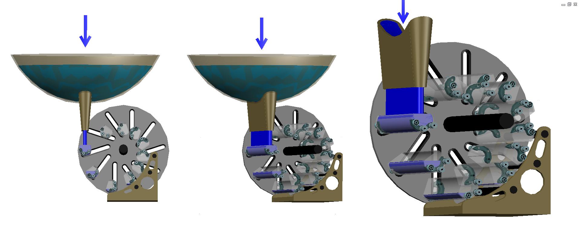
In Fig.58 is shown in three foreshortenings the appearance of such device.
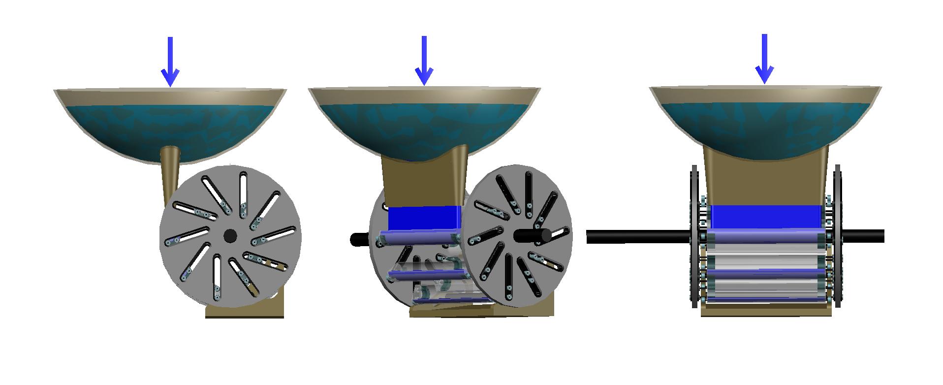
In Fig.59 the device is also shown in three foreshortenings, but without the front disk.
In Fig. 60 is shown the appearance of a disk equipped with ten inclined paths (disk intended for use in this embodiment of the rotor, that is different from the disks, intended for the previous embodiments, by the absence of covers which seal the outer sides of inclined paths).
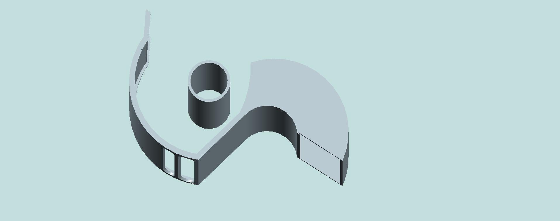
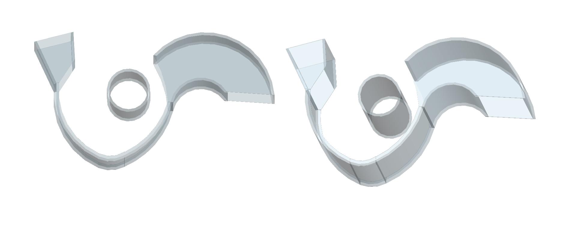
Design of hollow movable blades is explained by using Fig. 61.
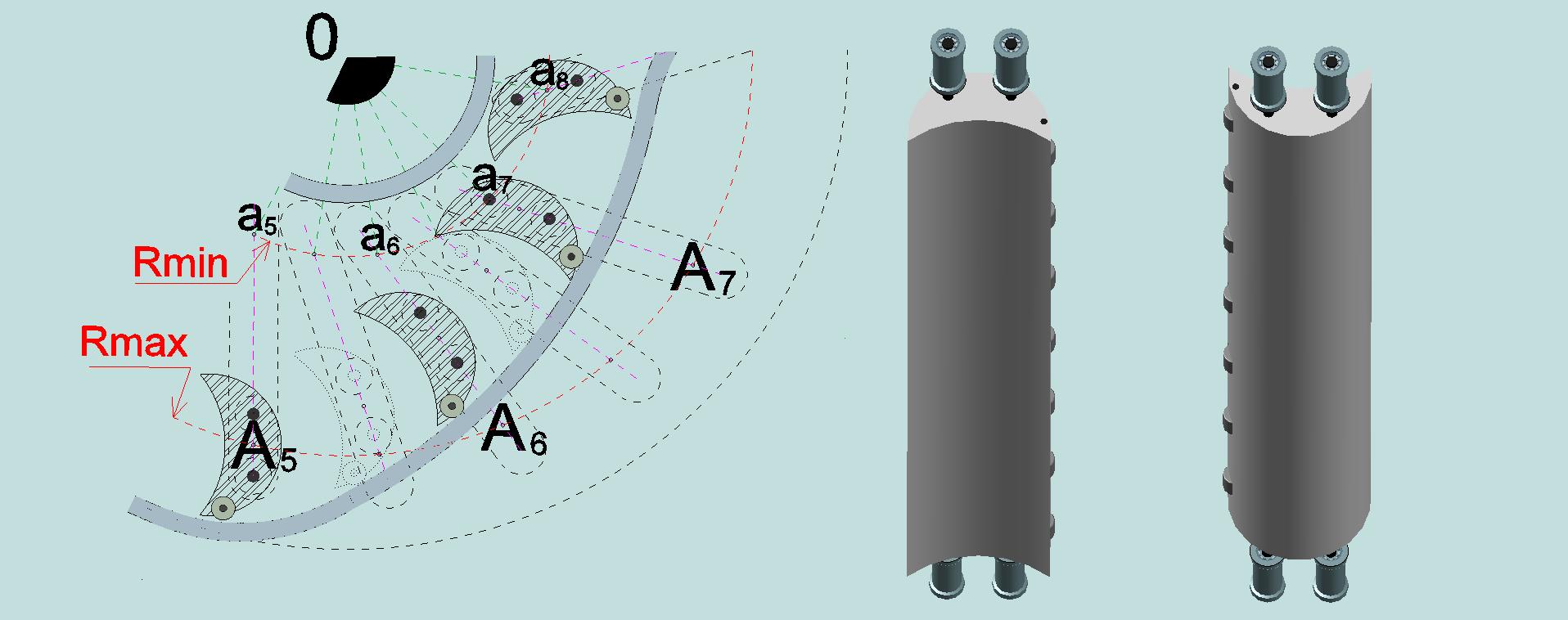
The body of the movable blade is shown, for clarity, by translucent color. It has a shape of a long hollow cylinder that partly sheared off from one side (Such form is like form of a long trough.). Inside the cylinder, at both edges, there are solid metal inserts carrying three axis, at the outer edges of which are fixed wheels - bearings. Larger wheels are intended to provide a linear displacement of the movable blades along the oblique tracks embedded into the disks. Smaller wheels are intended for rolling of the movable blades along two parallel tracks ensured by the special stationary device, during moving of the blades in the sector A5 – O – A7 (Fig. 62).
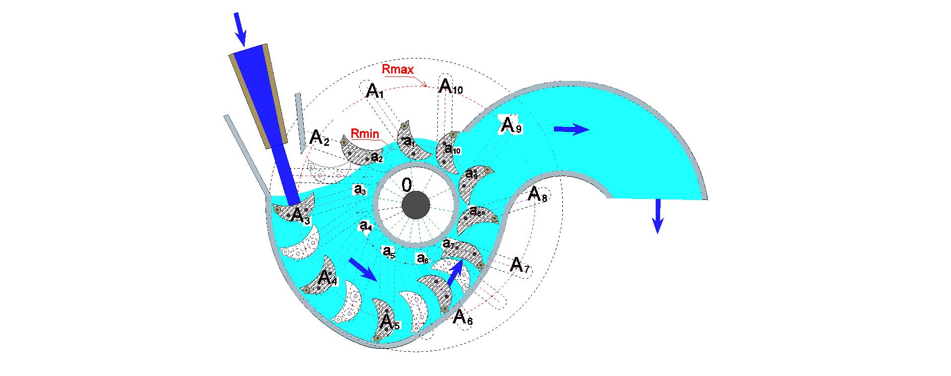
In Fig. 62 is shown the cross section of the engine rotor by the plane parallel to the internal planes of the paired disks and passing midway between them.
The circumference of maximum diameter which is shown here by a dotted line conditionally reflects projection contour of the disk on the cross-sectional plane. Cross-sections of the ten movable hollow blades are shown in the form of truncated circumferences with images of locations their centers of gravity by the points of black color, and with images (by dotted lines) cross sections and projections of the axes, and contours of the wheels which are at the ends of the blades. In the process rotation of the motor rotor the mass centers of the movable blades are shifting along the axes of inclined paths embedded in disks. In figure are shown by dashed lines of red color the circumferences of the maximum possible and minimum possible removal of the centers of mass of the movable rotor blades from the axis of rotation (from the point “O”) → Rmax and Rmin. Axes of the inclined paths, embedded in disks, are shown conditionally by dotted lines of crimson color. For clarity are also shown cross-sections of the movable blades in some intermediate positions of their displacement. At this, the blades are shown by dashed lines. By symbols a1 — A1 … a10 — A10 are designated places of possible location of the centers of mass of the movable blades at their minimum and maximum distance from the rotor axis of rotation (from the point "O"). In the figure is shown cross-section of nozzle designed to control the direction of water supply and increasing its velocity (the water is depicted in dark blue). The degree of filling by water the hollow blades, during their displacement in sector A3 – O – A6, is depicted in light blue. The movable blades, by the time of their approach to the sector A5 – O – A8, are became almost completely empty, and hence their weights tend to be the smallest. Under the bottom part of the sector area A5 – O – A8 is shown, by dotted lines, the projection of the outer contour of a stationary device, which forms the paths for movement along them of lesser wheels of the movable blades. Due to the design and location of this stationary device, lightweight movable blades gradually approach the rotational axis of the rotor, and after passage through the sector A7 – O – A8, during the movement in the sector A8 – O – A1, their centers of masses will be moving along the circumference of the minimum distance from the rotor axis → Rmin.
In Fig. 63 is shown the cross-section of the sector A5 – O – A8 in enlarged view.
The possible variant of design the stationary device comprising two curved tracks for movement, in the sector A5 – O – A8, of lightweight blades (the blades from which water poured out) is illustrated by Fig. 64.
During rotation of the rotor a jet of water falling from the nozzle, puts pressure on a counter movable blade. In Fig. 62 this is shown at the moment when the center of mass of the moving blade is aligned with the point A3. At this, allowable volume of the movable blade which was hollow before this moment is filling with water completely. As a result, the torque on the rotor shaft is created not only by pressure of water jet coming from above into that blade, but also due to the direct impact of gravitation on the mass (weight) of the blade filled with water. During further movement of the blades (in counterclockwise direction) the direct water pressure from the nozzle no longer acts on them. But the direct impact of gravitation on the masses of the blades, filled with water, continues. However, during further rotation the water gradually drains, that is the masses of movable blades are diminishing, and also are diminishing the adequate lengths the levers of rotation. But still! The net torque is increased and it increases the corresponding angular velocity of the motor rotor (what corresponds to the second law of classical mechanics) throughout the total period of movement of the blades in the sector A3 – O – A5, and not only during the direct impact of the water pressure from nozzle on counter blade. During further movement, in sector A5 – O – A8, the movable blades, will ascend to full convergence of their centers of gravity with the circumference Rmin. Then, movement of the lightened blades extends in sector A8 – O – A1, along the circumference Rmin, that is at the minimum distance from the rotational axis of the rotor. As a result of such the constructive directional movement of the blades is realized the mechanical advantage unequal-arm levers of rotation. The moveable blades, at their movement in the sector A3 – O – A5, are not only connected by their centers of gravity by the unequal-arm levers of rotation with the centers of gravity of the blades opposite to them, relatively to the rotational axis, but also have a significantly higher weight compared with them. By advantage of this embodiment is also that, thanks to the use of the stationary device for moving lightweight blades in sector A5 – O – A8, the losses of energy to lifting the blades in the direction Rmin are significantly reduced.
* * *
The motor, rotor of which is equipped by movable blades of similar design (by hollow and by lightweight), can be made even more efficient by ensuring water supply with aid of two nozzles. The second, additional, nozzle should be directed so that the water from it will put the most pressure upon the moving blade at a moment when its center of gravity crosses axis of the inclined path indicated in Fig. 65 by symbols a2 — A2. At this, the net torque of the motor shaft will be increased not only due to direct water pressure on this blade, but also due to the fact that the blade will fill up by water, the weight of it will become bigger, and will be accelerated its displacement from the rotational axis (the displacement in the direction to the circumference Rmax). As a result of accelerating elongation of the lever arm of rotation formed by the mass of this blade, filled with water, will be increased the share of the net torque generated due to the direct impact of gravity on the masses of the movable blades.
In Fig. 65 is shown the cross section of the motor rotor which is under the impact of the water pressure coming from the two nozzles. The plane of the cross-section is parallel to the inner sides of the coupled disks and passes midway between them.
In Fig. 66 is shown the appearance of such a device.
In Fig.67 this device is shown in three foreshortenings.
In Fig. 68 this device is shown without the front disk.
In Fig.69 this device is also shown in three foreshortenings, but without the front disk.
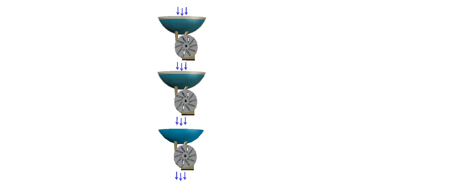
It is possible frequentative, sequential, the use of such engines under a single stream of water. An example of the serial cascading of such engines is shown in Fig. 70.
*
As a result, embodiments of rotor designs, with the use of lightweight movable blades of hollow shape, can provide with even greater efficiency the possibility of sharing harnessing the kinetic energy of the water falling from above on the blades of turbine rotor with kinetic energy of direct impact of gravitation on the masses of movable blades bonded by unequal-arm levers relative rotor rotation axis.
The use of designs rotors for hydraulic motors, according to a third embodiment, that is of such, which are equipped by the lightweight movable blades of hollow form, is seems particularly appropriate in areas with relatively small water head.
*
* * *
In the work of the all now-active hydropower plants the kinetic energy of the mass of falling water is not fully spent on ensuring of the force impact on the rotor blades of the hydraulic turbines. If the all potential energy, determining by the mass of falling water and by the height difference, at converting into kinetic energy, expended completely, the water, reaching the lower level of the height of the turbine base, would have stopped a further decline. But we know that this is not so.
In all of offered here options of designing rotors of hydraulic turbines are realized the additional use energy of falling water to ensure lifting of movable rotor blades and approaching centers of their masses to the rotor axis of rotation during the movement of the blades in the sector A5 – O – A8 (Look Figures 51, 57, 62 and 65.). As a result of forming the aforementioned trajectories of the movable rotor blades, their masses are become bonded with axis of rotation of the rotor by unequal arm levers, that provides the use of additional kinetic energy source - the energy of direct impact of gravitation on the masses of the movable blades bonded by unequal arm levers of rotation.
Thus, owing to proposed method of jointly harnessing the kinetic energy of pressure the water jet, that falls from height, on the rotor blades, and the kinetic energy of the direct impact of gravitation on the masses of the movable blades is opened the possibility of increasing the efficiency of the turbines hydroelectric power plants.
This Chapter was added 21 August 2016
This page was last modified on 12 June, 2017